Q-net cabling for serial devices
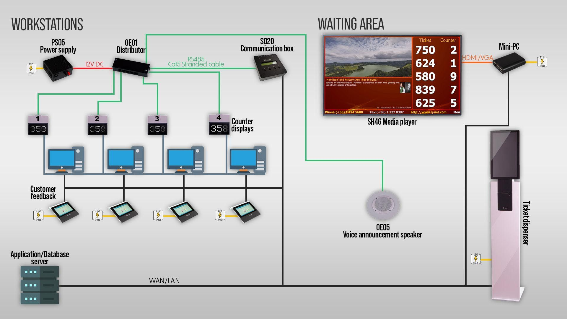
The Q-net system uses a tree topology for cabling. A tree topology combines characteristics of linear bus and star topologies. The devices are connected to the SD20 communication box through a distributor unit (OE01), with the exception of ticket dispensers and LCD displays (e.g., SH46). The connection method for ticket dispensers depends on their type. Ticket dispensers equipped with a PC or embedded controller are simply connected to the computer network. In addition, they only require a 230 V power outlet.
Q-net system cable connections
RJ12/6P6C (Connected to the distributor) preferred UTP cable pinout
 Pin1: +12V blue-white Pin2: +12V blue Pin3: Data A orange-white Pin4: Data B orange Pin5: GND green-white Pin6: GND green
For 8/8 RJ-45 connectors:

Connecting the devices
The devices are connected through the OE01 distributor.
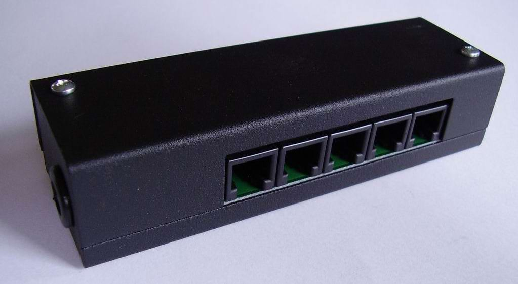
Connect the device cables to the distributor. If the system requires additional sockets, two or more distributors can be connected using a UTP cable. Each distributor must also be connected to a 12 V power supply. One UTP cable must be connected to one of the distributors and then connected to the SD20 communication box If multiple distributors are used with separate power supplies, the UTP cable connecting the distributors must not carry the +12 V power connection. Therefore, the blue and blue/white wires must be disconnected from the connector. Otherwise, the distributor and the connected devices may receive +12 V from another distributor's power supply. This can result in a high current flowing through the UTP cable and may cause the cable to overheat or burn.
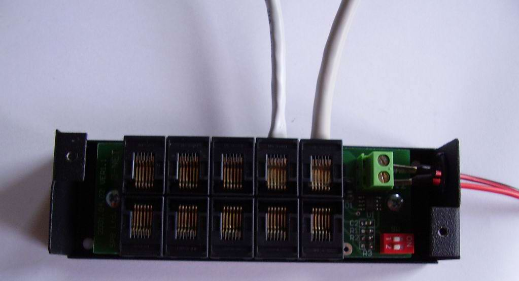
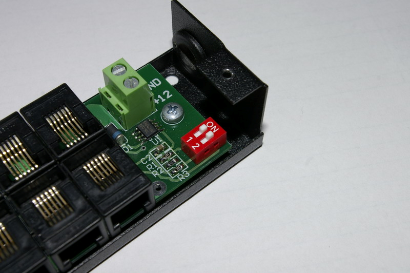
The DIP switch of the last distributor in the line must be set to ON (even when only one distributor is used). The DIP switches of all other distributors must be set to OFF.
Sizing the cabling
The system power supply provides 13.5V, 8A maximum. On a 2.5mm wire the necessary voltage can be transferred from the power supply to the distributor box to about 12 meter distance. The distance can be higher with more thick cable, or if less than 8A is necessary; 8A is the maximum load of the power supply, and this means 16 displays (500mA max consumption calculated for each). One distributor box has 10 sockets, the connection of 16 displays can be provided by 2 distributors. (1 socket also used for incoming data and 1 for output data to the next distributor).
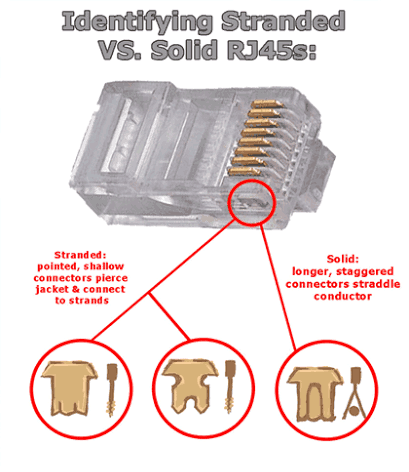
From the distributor to a display (2 pair of the UTP cable used to transfer the power) the maximum length is about 30 meters. The voltage dropdown in such distance is 1.3V (24 AWG cable)-2V (26 AWG cable), which is still acceptable, 9V is the minimum required voltage for the displays. With 28 AWG cable the resistance is higher, the best is to use 24 AWG cable type. Actually also the resistance of solid UTP cable is lower, so it is better from this point of view, but make sure that the correct RJ12 plug used, which is designed for solid cable.
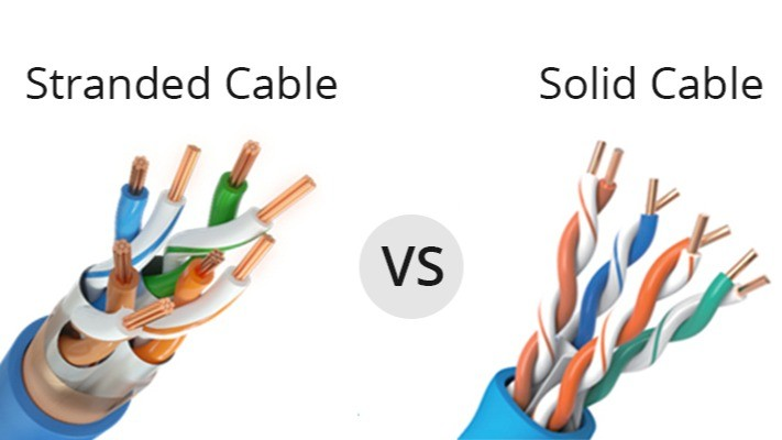
This image shows the difference of a plug designed for solid/stranded cable. (The example is RJ45, but RJ12 used for the displays)