Administration - Branch - Devices
Device controllers
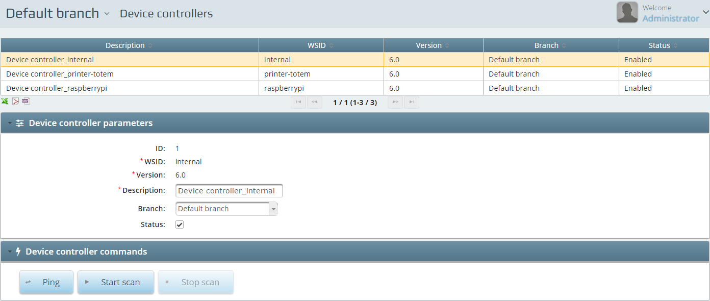
Every installed system has got one internal device controller added. Device controllers are mainly responsible for device communications. All the configurable and non-configurable devices will connect to the set controller.
Device controller parameters
The WSID of the device controller is the identifier of it. Version is the actual version of the device controller. Description is going to be acting as the name of the device controller. These fields are mandatory if setting up a new controller. ID is generated by the system. You need to select the Branch which the controller is going to be assigned to. You can enable or disable the controller with Status.
Special configuration
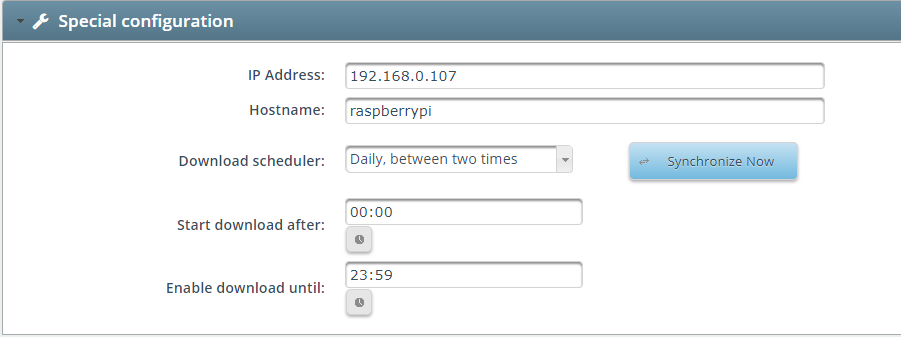
IP address & hostname fields are not neccessary to fill but if you do it is easier to track your devices and device controllers.
Download scheduler : Can be set to 3 different modes, which are:
- Daily between two times, means that you can give two date&time where between the synchronization occurs
- Permanent synchronization, which means every time a new file appears at the congiuration, the DC will instantly download it to it’s device
- Disable synchronization, which means if you set this you turn off completely the synchronization
When you make changes to the files for example at Media player and you want them to instantly appear on the given device, you can force a synchronization with the button Synchronize now.
Device controller commands
You can Ping the controller to see if it is online or not. If you click on Start scan it will find the configured and connected SD20 communication boxes and printers. For SD20 Communication box settings please see section 6.2.
Communication boxes
How to configure SD20
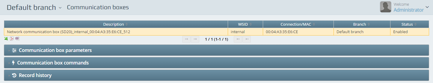
Once you have a configured SD20 communication box set up in the system you will be able to see it in this menu point after running a scan in the device controllers commands – see section 2.1.3.1.2.
To configure the SD20 communication box you will have to have the device connected to the network and have the device in hand or a configuration web interface open.
Menu and settings of the device
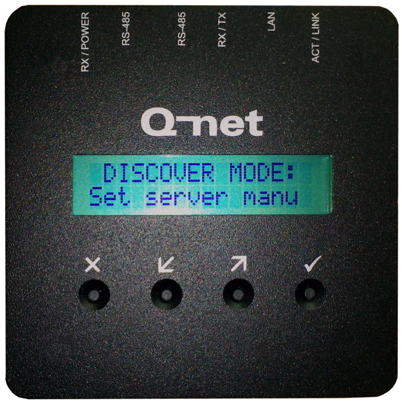
After power on the device, the firmware version number and the „Press a key to configure…” message will appear on the display. Press any button to enter to configuration menu. The menu items can be selected by pressing the arrow buttons. To select a menu item, or apply the modification, press the √ button. To cancel, and exit from the menu, press X.
Menu items:
„No discover – Auto discover” – After entering this menu, there are two options: “Set server menu” and “Find server auto”. The automatic server detection is using broadcast messages on UDP ports, so it is working only in case this type of communication is enabled on the network (no router should separate the server and SD20). In case you choose “Set server manually”, other menu items will be available where you can enter the server parameters.
„Change host name” – The device already has a default host name, e.g. QNETE6CD. You can modify this name with the buttons: X button deletes back one character, the Up/Down arrows are selecting a letter, and the √ button jumps to the next character. To keep the changes, hold the √ button for a few seconds, and press again when the Store [Y/N] message is appearing. (Or get back to the menu without saving it with the help of the X button.
„DHCP enabled – DHCP disabled” – Depending on the network parameters you can use automatic IP address for the device. Enable the option if your network is using DHCP server to provide IP addresses.
„Conn. type (IP) - Conn. type (NAME)” – These option allows in case of manual server / device controller settings, to use host name or IP address at the server settings. (See next menu item)
„Server IP Addr. –Chg. server name ” – Depending on the “Connection type” menu settings and on “Discover” settings, you can type the IP address or the hostname of the server or the device controller ; X button deletes back one character, the Up/Down arrows are selecting a letter, and the √ button jumps to the next character. To keep the changes, hold the √ button for a few seconds, and press again when the Store [Y/N] message is appearing. (Or get back to the menu without saving it with the help of the X button.
„Change Port” – The device is using TCP connection to communicate with the Q-net server / device controller software. The same port number configured in the server software should be used for SD20. (In case of Q-net Pro v5 and V6 the default port number is 8000.)
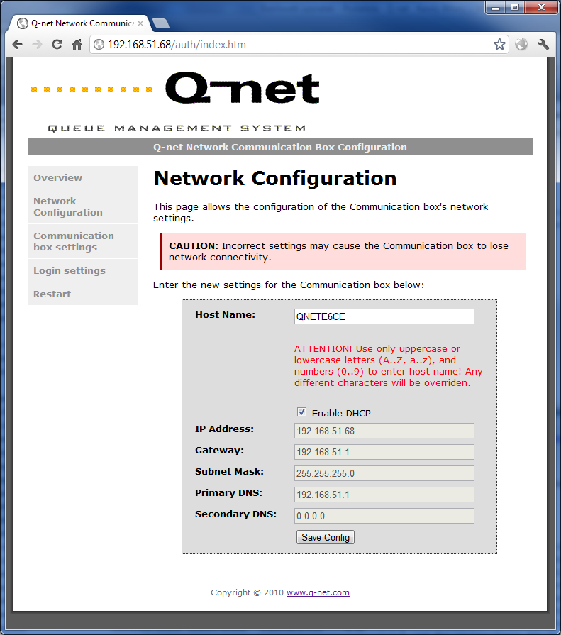
Configuration on web interface

The SD20 allows configuring the same settings on web surface as well.
This requires working network connection. The webpage can be opened by typing the IP address or hostname to the browser’s URL field.
The settings are password protected, the default username is “admin” and the password is “1234”.
Lost password and factory settings can be restored in the following way:
During power on, hold the 1st, 2nd and 4th buttons of the control panel.
“Config reset” message will appear, showing that the default settings were loaded.
Firmware upgrade process
Type the link http://QNETxxxx/auth/upgrade.htm to the browser, where “QNETxxxx” is the hostname of the SD20, (Ip address can be also used) and follow the instructions.
The firmware upgrade takes few minutes, during the process don’t turn off the device, and wait until restarting automatically. After finishing the upgrade “Page cannot be shown” message might appear in the browser, this is normal.
Communication box parameters
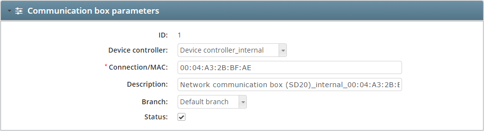
Once the SD20 communication box is set up to connect to the device controller the parameters should be changed/viewed here. Selecting a Device controller if you have more configured. Connection/MAC shows the MAC Address of the device. The Description will identify this SD20 in the system with a name. You can assign it to branches with the dropdown box of the Branch.
Communication box commands

You can Ping the SD20 communication box to see if it is connected to the network or not and you can Start scan for connected devices to this communication box.
Ticket dispensers
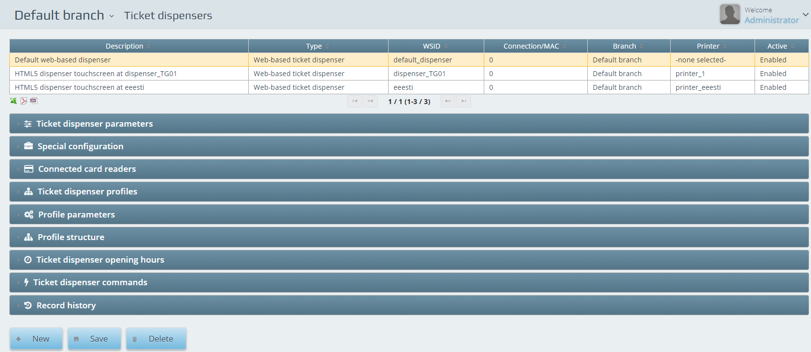
One of the main elements of the system. You can configure the ticket dispenser on this page.
Ticket dispenser parameters
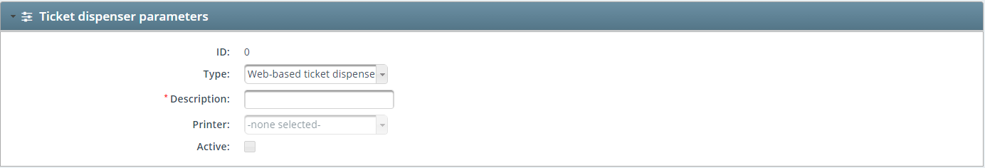
You can configure the assignment and the hardware parameters of the dispenser starting from selecting dispenser Type. This can be web-based or Push button dispenser (TG17). WSID is going to be the identifier of the entity. Description is used like a name for the setup. The tickets will be printed on the selected Printer from the drop box menu.
Special configuration
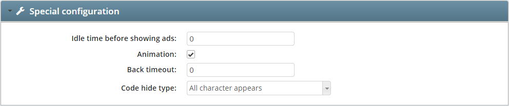
Special feature of a ticket dispenser can be configured. Advertisement can be set so the dispenser will act like a billboard while idle. To set the feature you have to add an idle time at the Idle time before showing ads in seconds. Animation enabled will end in a smooth overlap between the pictures showing up on screen. Back timeout is a timeframe for returning to the main screen if customer has ended the selection procedure without successfully selecting a service. If there is customer identification configured in the actual setup the code entering method can be selected at the Code hide type. All character can be either shown or hidden or we can let the last character appear.
Connected Card readers
If there is a Card reader added to the dispenser you can select it here from the available list.
Ticket dispenser profiles
You can select the assigned profiles to the dispenser by marking them besides the names of them. You can also drag and drop the profiles: the one on the top has the highest priority; the one on the bottom has the less priority, and so on.
Profile parameters
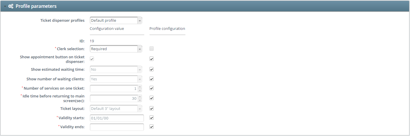
At Ticket dispenser profiles you can select one of the__ profiles that were prepared in the Central management section. Clerk selection__ can be disabled, required – and set to optional. Appointment can be enabled with Show appointment button on ticket dispenser marked. Show estimated waiting time and Show number of waiting client will reflect the amount of customers in the queue. Number of services on one ticket can be the maximum of selectable service for a ticket. Idle time before returning to main screen is the time limit of available item selection. After the set time value the screen will automatically return to the main screen. Ticket layout is to set the printers parameter by selecting the 2” or the 3” one. Validity of a profile can be set with the help of Validity starts and Validity ends set. There is always an option to override the values with the Central profile setup under the Profile configuration.
Profile structure
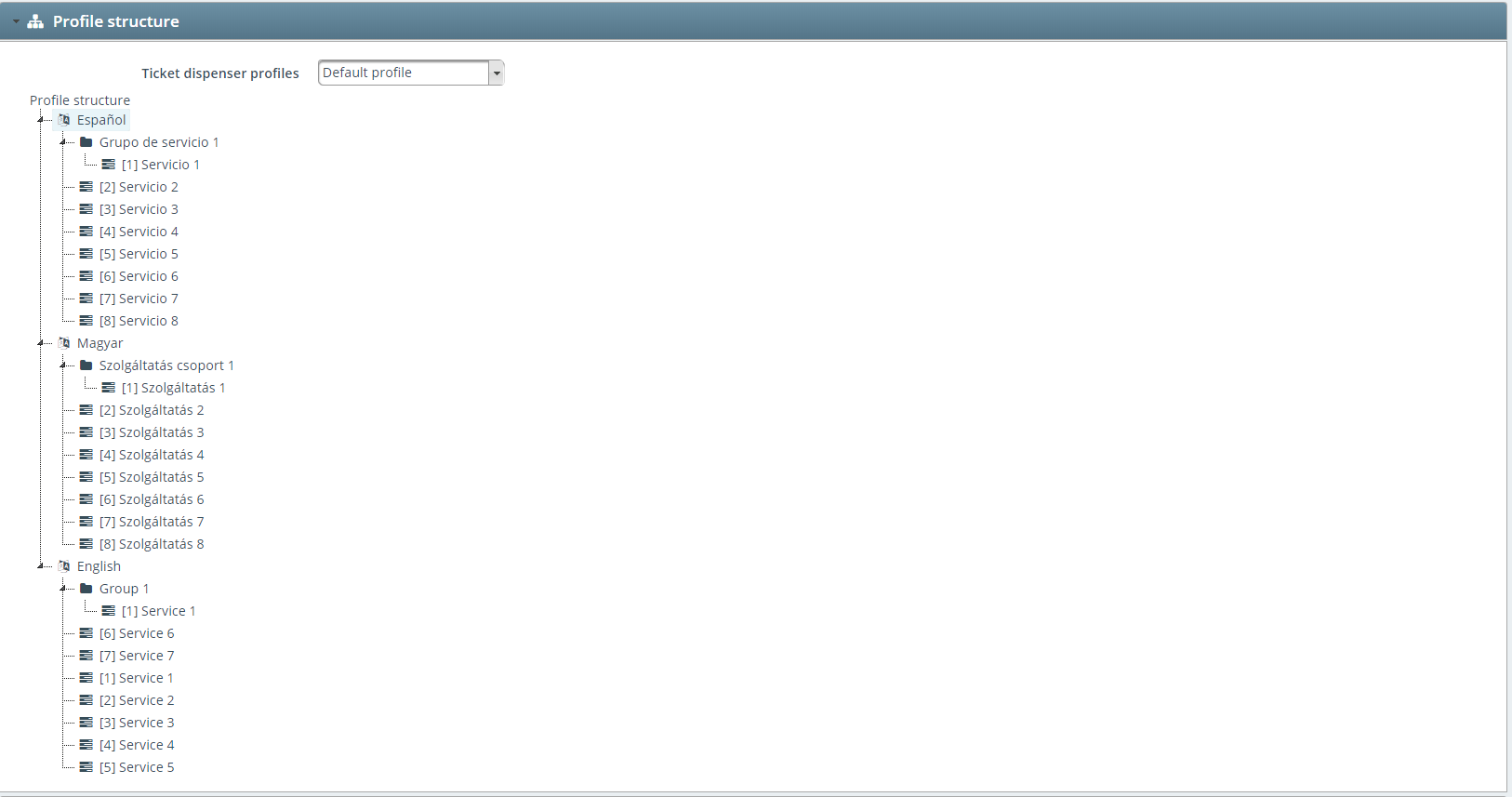
Here you can see your Ticket dispenser profile structure in read-only mode, so you are not able to modify it at this tab. To modify go to CENTRAL SETTINGS / Ticket dispenser profiles / Profile structure .
Ticket dispenser opening hours
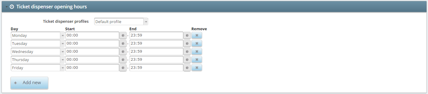
After selecting the profile the opening hours can be set up via the client policy or based on individual plans. Days and the time (Start and End) can be set with the help of the selection buttons and you can create several opening hours per day to include lunch breaks too.
Ticket dispenser commands

You can check the online availability of the dispenser by Pinging it. Also you can initiate a Print test with the dedicated button. Refresh screen is a button to refresh the screen as it says so.
Ticket dispenser setup
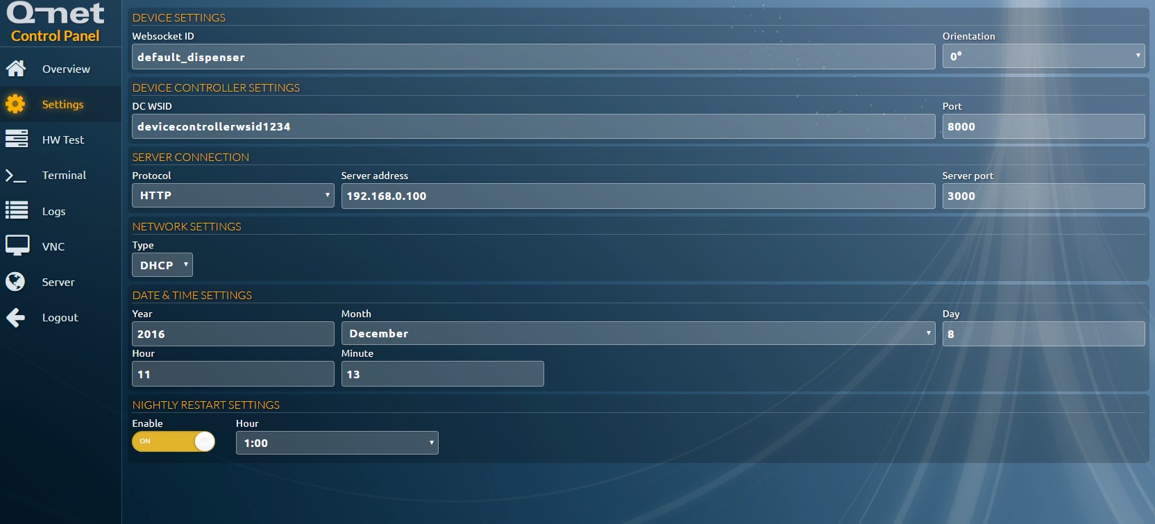
On the ticket dispenser you should set the network parameters, or leave it on automatic DHCP network settings, in case DHCP server is available in the network.
You can set the connection settings on both the ticket dispenser touch screen or by entering the IP of the device to a browser.
Enter the IP address or hostname of the Q-net server, set a unique websocket identifier (WSID) for the modules running on the ticket dispenser: These are the ticket dispenser and the device controller applications.
The WSID should be unique! Then press “Save”. The default connection port is 3000, you have to change it to different value if it had been changed in the application server settings,
Make sure that the port is open on the firewall.
After the device connected successfully, the ticket dispenser and the device controller should appear automatically in “Default branch” on the configuration page.
Printers
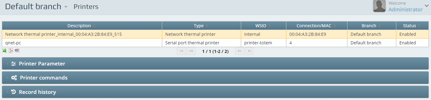
Printer of the branch is a printer that is recognized by the device controller on the machine. This means if you have a shared printer added it will be also recognized. The ticket dispensers have serial port built in printers. If a device controller is installed on a ticket dispenser – the built in printer is going to be automatically registered. If the printer is not detected you should add it manually as a Serial port printer. The printer port can be known from the Device Manager of the OS. You can also add new printers to the system with the New button.
Printer parameters
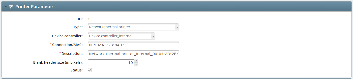
You can select the Type if adding new printer or modifying existing one.
Device controller will need to be selected to refine the setup. Depending on the type of the printer all necessary connections parameters need to be entered which are listed.
You also will need to add a Description as a name for the printer. Blank heather size (in pixels) can be set if you find the top space of the printed ticket too short. ( We recommend to set this parameter to 15 pixels! )
Printer commands

You can Ping the printer and initiate a Print test.
Card readers
If you have purchased a ticket dispenser with a built-in card reader there will be an entry here. You can add one anytime filling the required fields after pressing New button.
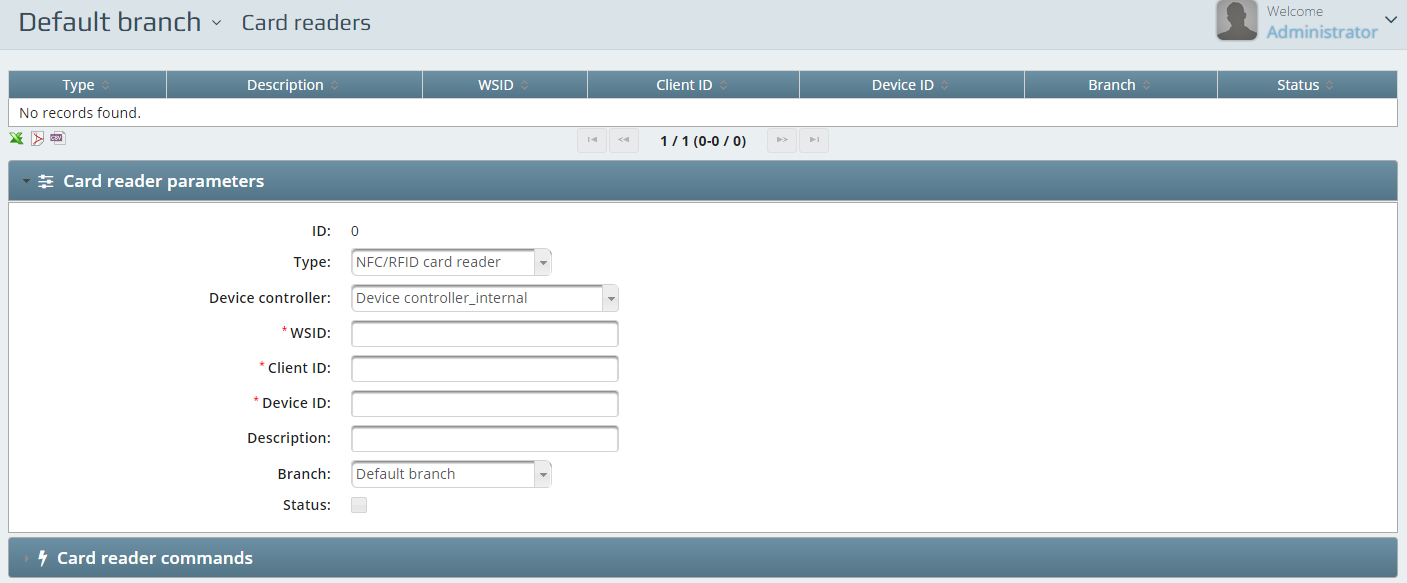
Card readers parameters
First you need to select the Type and the Device controller. WSID, Client ID- and Device ID is something that the reader carries as an information about itself. An installed device will have this information already filled.
Description is a name for the device to identify. You have to assign the device to a Branch.
Card readers commands
You can check the availability of the device here.
Counters
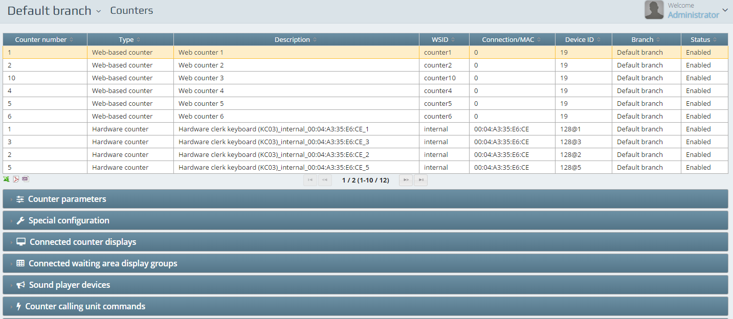
There are six web-based counters preconfigured. You can add or modify the number of counters your certificate allows you.
Counter parameters
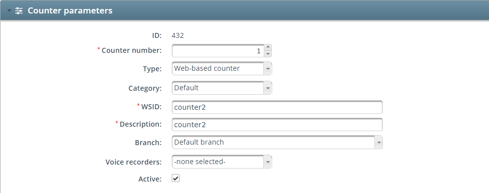
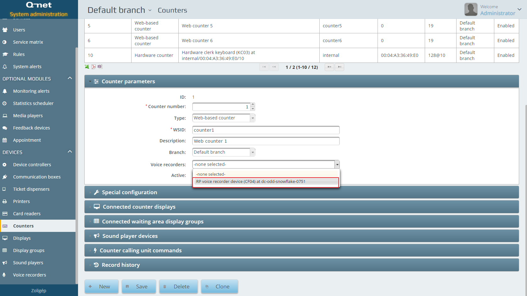
You need to set the Counter number and select the Type. Type of the counter can be web-based or hardware. WSID of the counter is the identifier or so called name of it. The counter has a Category as well;it can be Sit, Stand and Consultant. It also need to be assigned to a Branch. If you bought voice recorders for your server you can assign the Voice recorders to counters at this stage.
Special configuration
You can set the web-keyboard Animation and can set the Room number for the counter if there is any.
Connected counter displays
The system will show the list of the connected (detected) displays within the branch so you will need to select the one that should be assigned to that counter. Simply mark the checkbox and save the setting. When you configure the next counter the not assigned displays will appear only.
Connected waiting area display groups
The detected waiting area displays can be selected here. We call them display groups. One counter can be assigned to any number of waiting area display (group)s. In case for example there is a bank with 10 counters and 2 of them are the cashiers you can show their calling info on the waiting area display group for general calling info and on another one that is mounted above the cashiers but you can configure that on that waiting area display group only the cashiers calling info will appear.
Sound player devices
This area will list the available sound devices and you have to assign one – if any exist. This solution enables similarly to the above example about the bank that the display group dedicated for the cashiers can have a separated sound player device and this gives a sound only if a customer waiting for the cashier is called while another sound player device will give the sound at every call at the main waiting area display group.
Displays
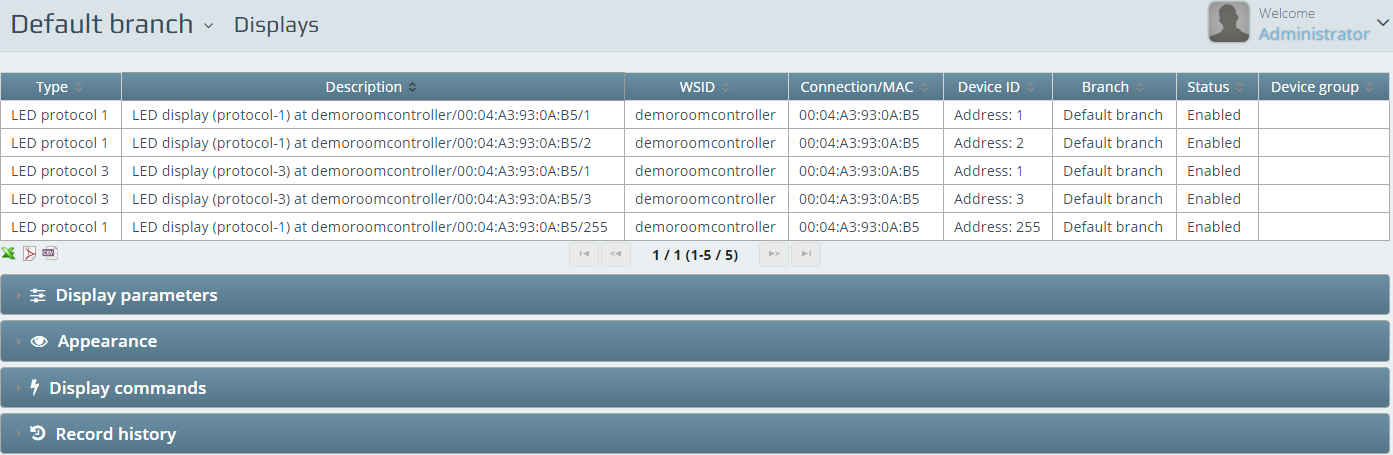
All connected device is registered automatically which is connecting to the branches device controller. So does all the displays. You can anytime add new displays with the New button.
Display parameters
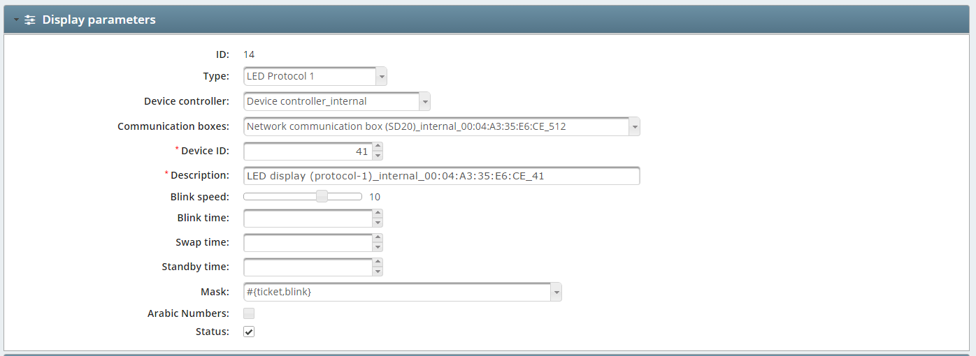
The Type of the display is identified with its communication protocol. Please check the below list to configure them on the right way:
LED Protocol 1: DG01, DC01, DG02, DC02, DG05, DC05, DG55, DG56, DC55, DC56, DC65, DC66, DC75, DC76, DB01, DB04, DB05, DB06
LED Protocol 2: DG04, DG60
LED Protocol 3: DS04, DS08
LCD Customer feedback: Only for CF01 Customer feedback device – this can act as a counter display as well.
You have to select a Device controller if you are adding one new display. Communication boxes have to be selected in case there are more in the network. Device ID is the actual displays hardware ID.
Description should be the unique identifier or name of the display. You can set the Blink time with the help of the slider bar. By default the blinking speed is set to 10. You can set a Blink time value which is given in seconds. Swap time is used if the Arabic numbers are checked in and the end user requires seeing “English” and “Arabic” numbers swapping: the length of the 2 ways should be set here in seconds.
Standby time is to configure the display when to turn off in case it’s idle. There are Masks for complex protocols. These masks are to set up various predefined solutions of customer awareness. Arabic numbers can be displayed on most of our displays in case this option is enabled.
Appearance
Selecting a display and configuring the appearance will result the displays final setup. Each and every display can be separately set up – as per the allowed protocols (depending on the type of the display) – how the client is going to use it. Grouped displays also can / needs to be set here if there are special ideas about the look of the calls.
Display commands
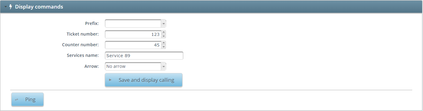
The section allows the administrator to test the displays by selecting the Prefix and setting up a desired Ticket number and Counter number to lit the displays. In case of Protocol 3 displays a service name can also be scrolled across the display as per the setup in the appearance section. The Arrows selection can also be tested with the ideal displays in the setup. You can ping a display from here with the Ping button.
Display groups
Display groups are usually for waiting area displays but configurations may differ.
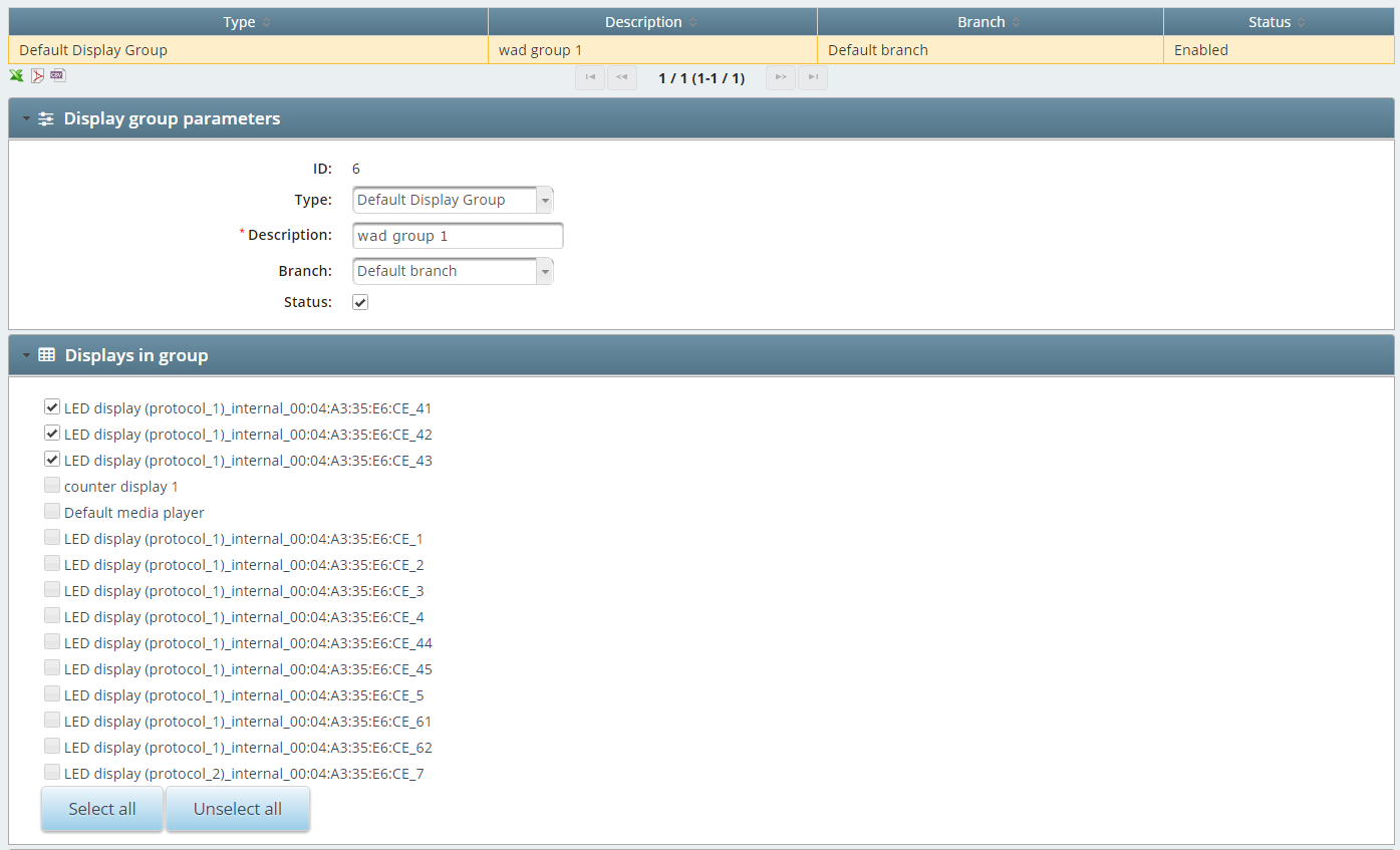
Display group parameters
When creating a new display group you need to add a name or a Description as a minimum. You can assign it to a Branch and select the group Type.
Displays in group
The available display list appears on this stage. You can mark and save the ones you like to group.
Sound players
If the PC which the system has been installed on had a configured sound device – it will be listed here.
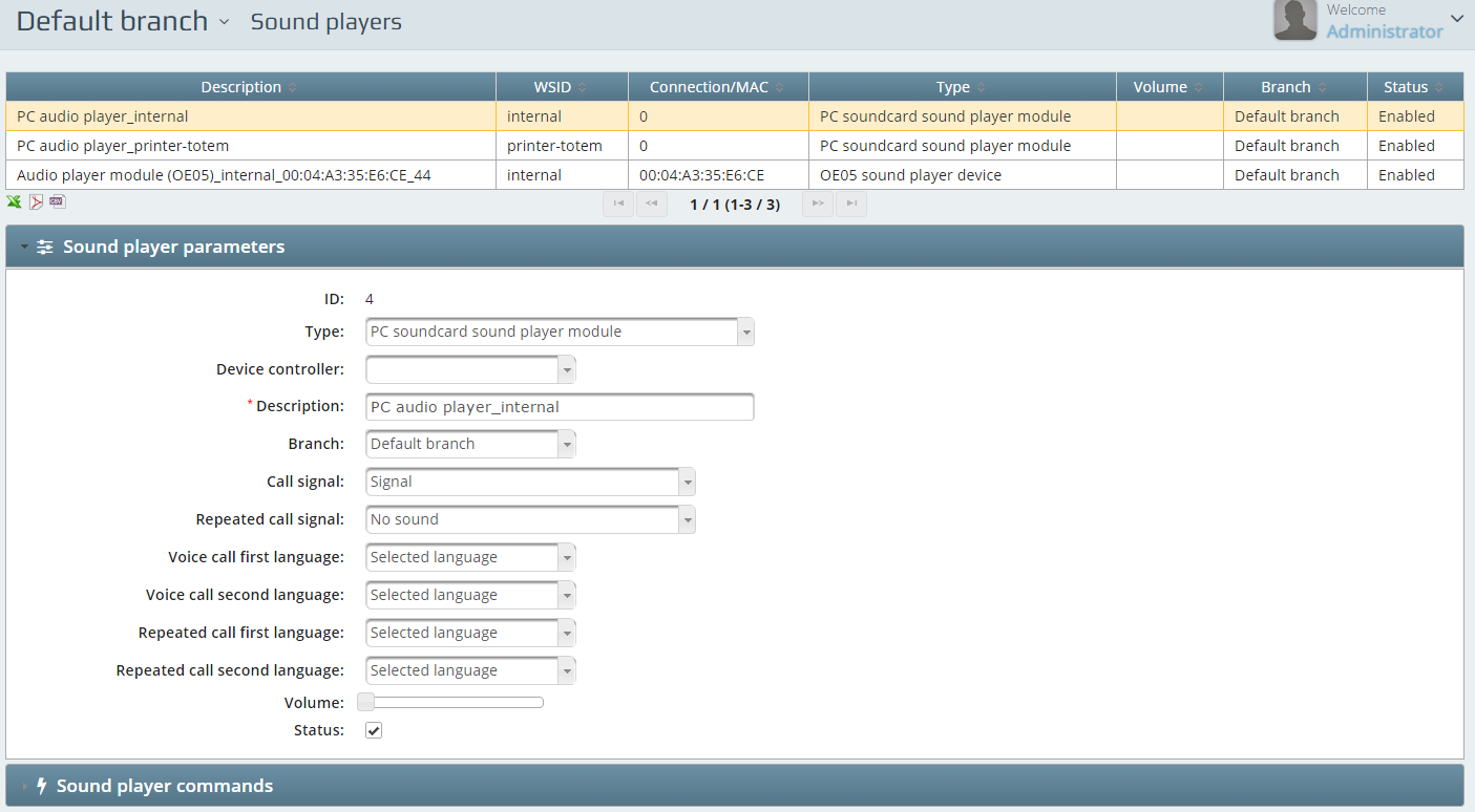
Sound player parameters
If you set up an audio device you need to make sure what are you configure. Selecting a Type is a good start. You will have a web-based option (Audio player device (browser and JavaScript)), OE05 sound player device and the PC soundcard sound player module as available ones.
Setting up the devices will be continued with the Device controller selection. In case of OE05 sound player device you will need to add the Device ID as well. Name the device – or add a Description to identify it. Assign it to a Branch. Select the Call signal and the Repeated call signal for primary sound notification. Set the Voice call first language and the__ Voice call second language__. If you want to call the languages on the selected services language – you should use the Selected language answer possibility. You can set the repeated calls first and second language as well with the help of the dedicated areas: Repeated call first language and Repeated call second language. Set the systems Volume with the help of the slider bar.
Voice recorders
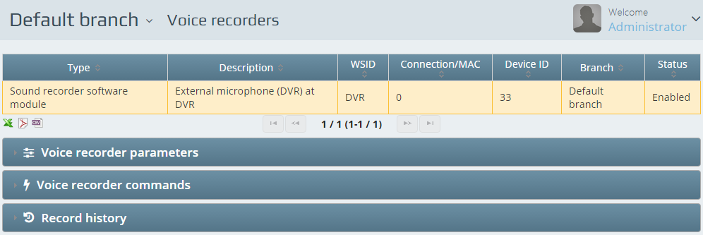
With the help of the Q-Net Digital Voice Recorder module you can add sound recorder modules to each or specific counters. To be able to set this feature you need a voice recorder, connected to the server.
Installation of the Voice recorder
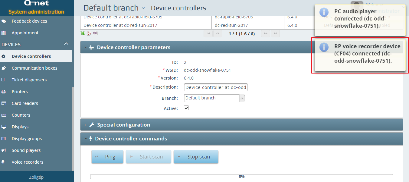
Connect the voice recorder to the network and connect it to the server. It is possible by entering the IP address of the device to a browser and configure it with the firmware. The device controller will connect in and you will be able to see it on Device controller list. Star a scan on the voice recorders device controller and the system will autodetect the new voice recorder device.
The voice recorder is now detected, so it needs to arrange to a counter:
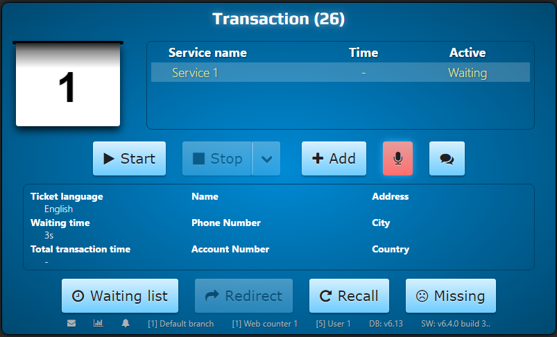
The counter now has a microphone icon. It indicates that the voice recording is now active. It is possible to stop the voice recording, by pressing the red button with the microphone icon.
The system will need some time to convert the voice record and send it to the server from the voice recorder. This process takes around 2-3 minutes.
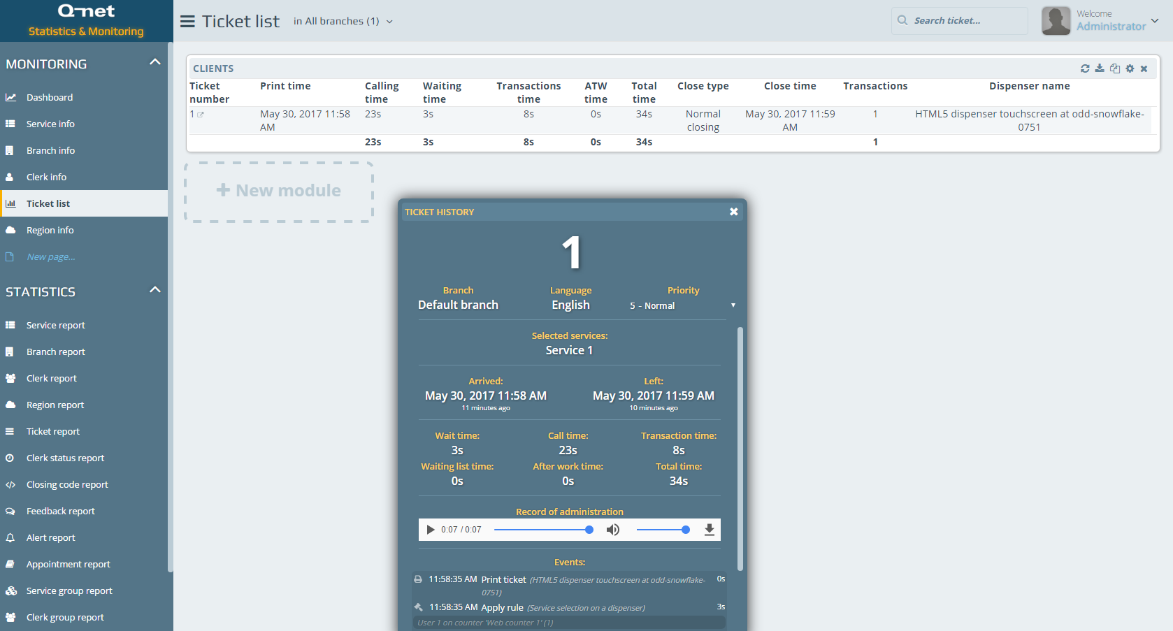
After the process is over, you can listen the record on the Statistics page, by selecting a ticket from the list.