Getting Started - Cabling
Cabling diagram
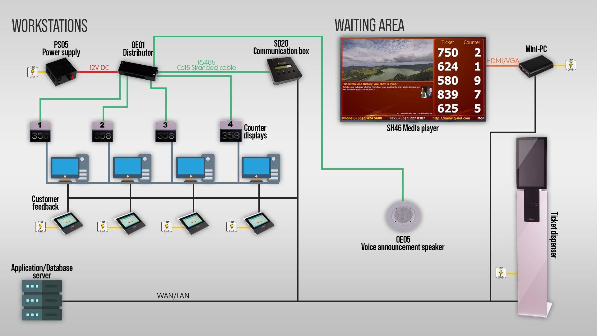
The Q-net system requires a tree topology cabling. A tree topology combines characteristics of linear bus and star topologies. The devices are connected to the controller PC through a distributor unit (OE01), except the ticket dispenser, and LCD displays (e.g.:SH46)
The connection of the ticket dispensers depends on its type. The ticket dispensers which are containing a PC, or embedded controller are simply connected to the computer network. Besides this, only a 230V power point is necessary for them.
The cabling depends on the different displays types as well:
The small (57mm digit) displays and the DG series waiting area displays are receiving the power from the distributor, which is connected to the power supply.
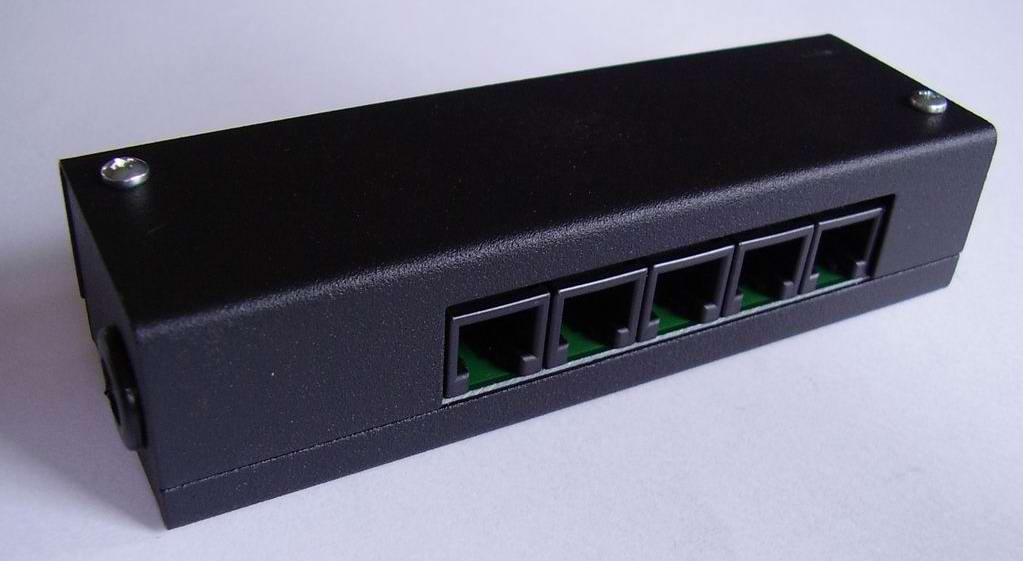
Q-net system cable connections
Phone connector 6/6:
(Connected to the distributor)
Preferred UTP cable pinout
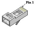
Pin1: +12V            blue-white

Pin2: +12V            blue

Pin3: Data A        orange-white

Pin4: Data B        orange

Pin5: GND            green-white

Pin6: GND            green
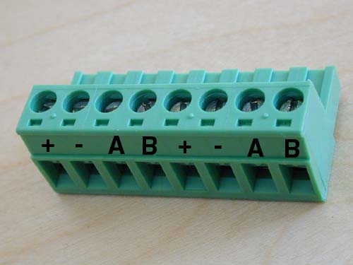
Waiting area display’s connector:
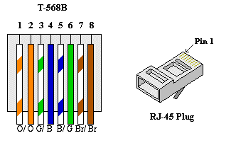
For 8/8 RJ-45 connectors:
Connecting the devices
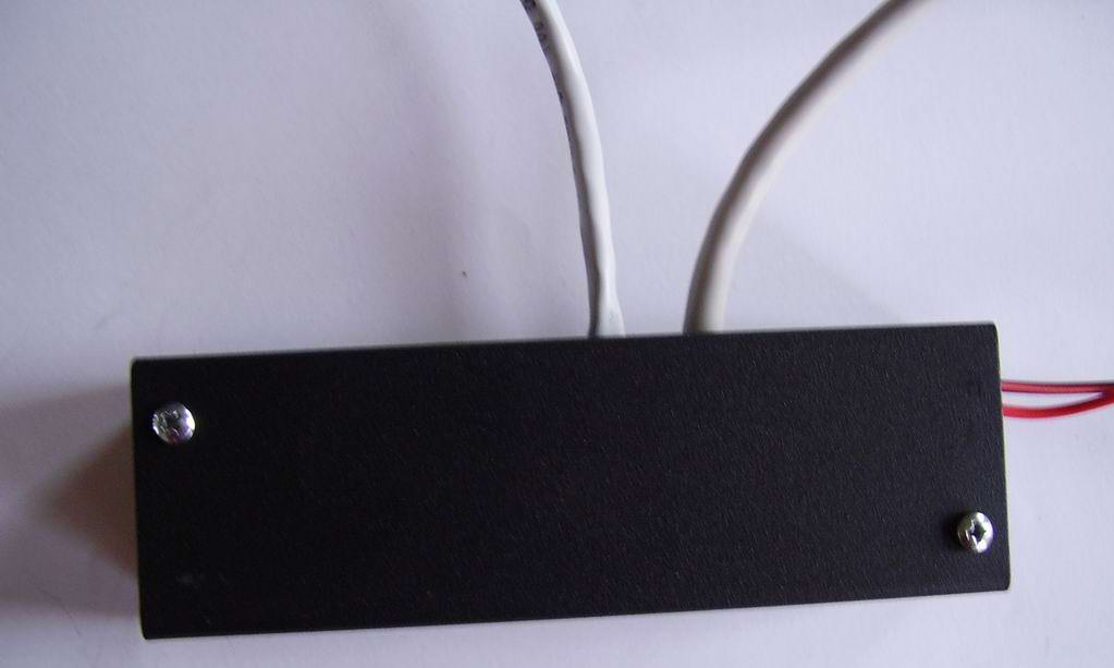
The devices are connected through the OE01 distributor.
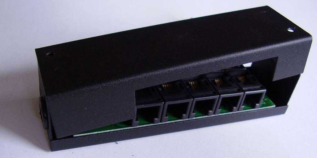
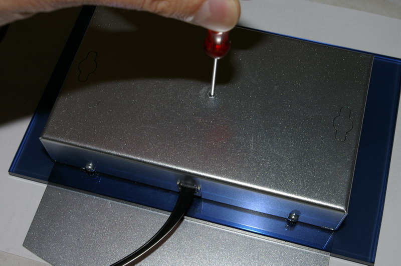
Remove the cover of the distributor.
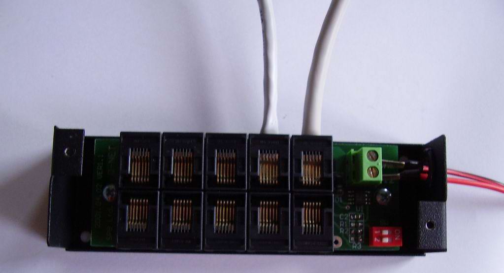
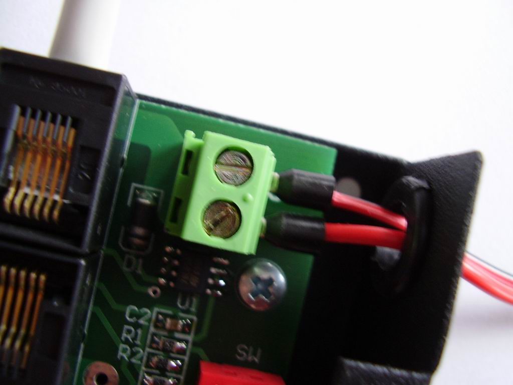
Connect the cables of the devices (displays, keyboards). If the system requires more sockets, simply connect two or more distributors with a UTP cable. And connect them to a power supply. (The other distributors also require 12V voltage)
Also connect one UTP cable to one of the distributors, which will be connected to the communication card of the Server PC. In the case when more distributors are used with more power supplies, the UTP cable which connects the distributors should not connect the +12V power. That means the blue and blue-white wire should be cut from the plug. Otherwise the distributor and the connected devices will receive +12V from the power supply connected to another distributor. This might cause big current strength on the UTP cable and it might burn!
The connection of the power cord.
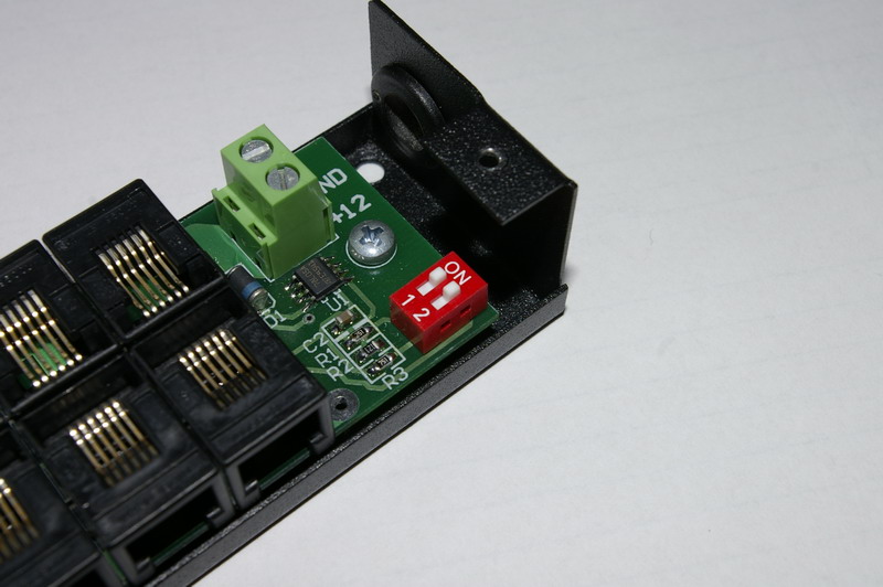
The Dipswitch of the last distributor in the line must be switched ON (even if you’re using only one distributor), but all the other distributors must be switched OFF.
When you’re ready, put back the cover.
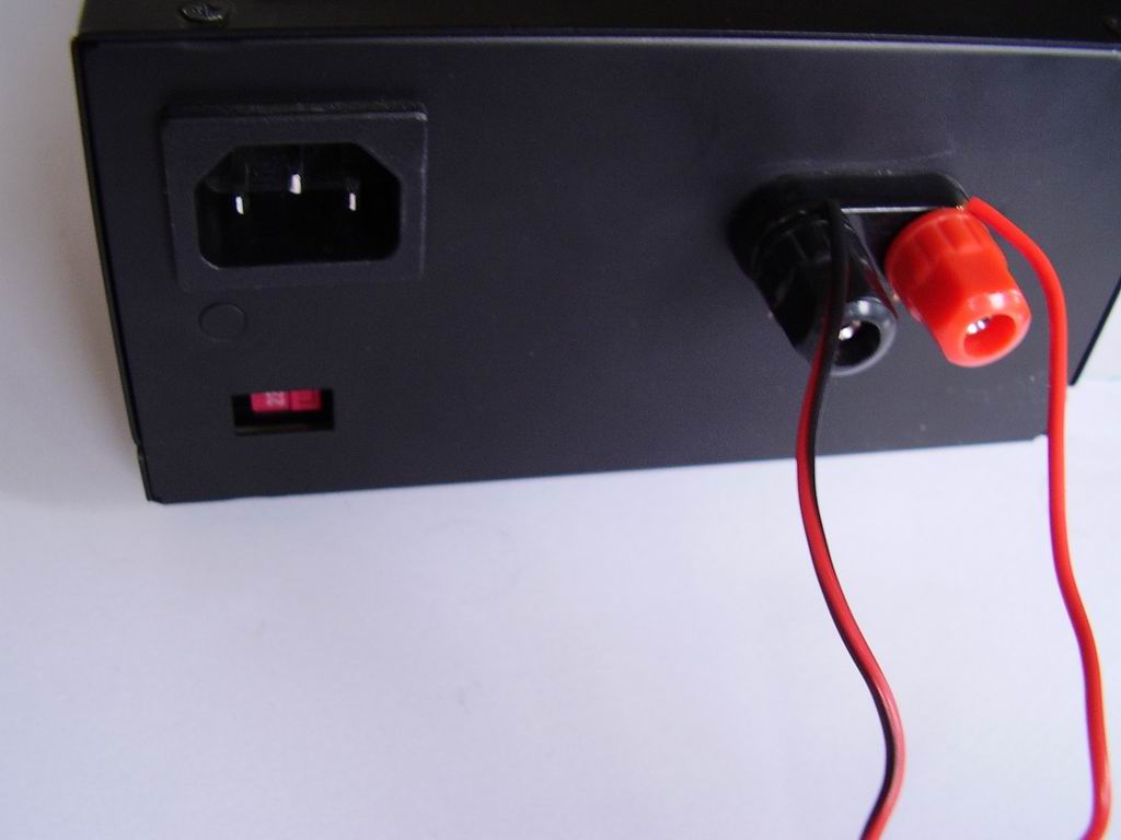
For the power supply, use at least 2mm diameter cables.
(It depends on the distance between the power supply and the distributor. For longer distance you have to use thicker cable to avoid the loss of voltage)
Setting the ID number of the Devices
The Q-net software identifies the devices (keyboards, displays) upon their Device ID.
Each device in the same category (e.g. Displays) must have a unique ID.
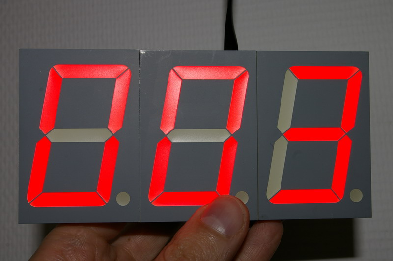
To check the ID of a unit simply plug in. When it receives its power, it will show the present ID number.
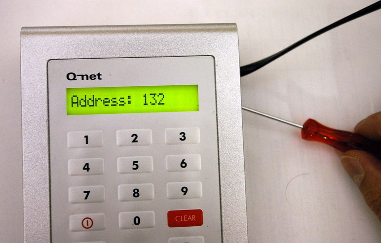
To change the ID of a unit you have to press the button on the back of its electronic board. In case of the keyboards (KC02, KC03), it is not necessary to remove their cover, dip into the hole with a thin object (e.g. screwdriver, paper clip), and press the button.
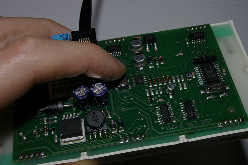
For the first press of the button, the present ID will appear, and every time you press again, it will increase with 1. If the demanded ID showed on the display, release the button, and wait until the display cleared. That means the new ID has been saved.
The device IDs are adjustable between the values 1-255.
It is recommended to set the same ID for the keyboards and counter displays as the number of the counter. For the waiting area displays it is recommended to set 41-42-43, etc… IDs for one display group, 51-52-53, etc… for the next group and so on.
The device ID should match with the settings of the relevant device in Q-net device configurator:
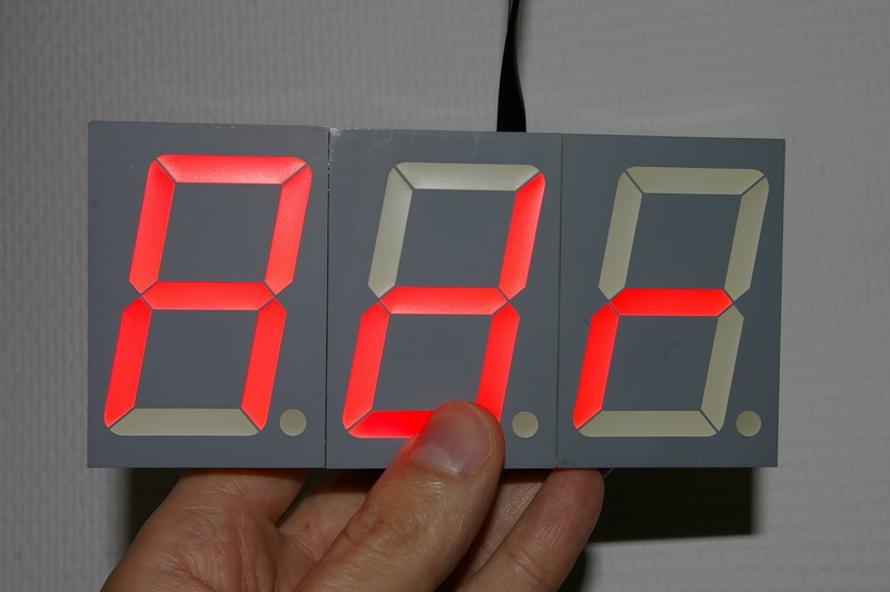
After the “Adr” text the display shows the current ID.
For a plain installation it is practical to set the device ID to equivalent to the counter No. For example for counter 1, set the keyboard and display IDs, to no. 1.
The ID of the displays can be adjusted through the hole on the back cover.